“You must have had a fun childhood.”
At the age of thirteen I was drafted.
Having for some time been an inmate in that sort of minor English public school which sees its purpose as feeding Sandhurst and in which the names of the dead go all along the wall of the Chapel and all around the Garden of Remembrance (and not every school even has one of those), and not having the sort of parents who would insist upon, and if necessary pay extra for, some soft option like the so-called ‘Social Service’ (who went around mending things) or the ‘Pioneers’ (who went around breaking them again), or even the Naval Section (about which others must reminisce, the veil of decency having been drawn), I was when the time came duly drafted into the Army section of the CCF.
Paris having only recently very nearly fallen to the Situationists someone clearly thought we’d be needed for something real before long and so we did very little of the chocolate soldiering so common in more effete cadet forces (e.g. we once visited another school where all they ever did was incredibly complex marching and counter-marching in a rather showy American manner accompanied by a vast and well equipped band, all this being done in mediaeval ecclesiastical costume) but instead went to cool places and got trained in cool stuff by the likes of the Ghurkas and the SAS.
Alas this idyllic state could persist only so long and having completed what they called basic training I then had in theory to choose a specialisation. However the Major in command of the whole circus (who looked, as he was so often reminded, like Klaus Fuchs and who in his spare time taught geography) somehow found out that my father when at the same school some decades previously had distinguished himself by (probably meaning ‘was beaten for’) having made a television receiving set from a war surplus radar tube and some other stuff, and without further ado put me into Signals.
The signals section occupied the top floor of a ratty old town house (the middle floor was a photographic darkroom and the ground floor a secondhand school uniform shop) on the other side of the road opposite the school’s ancient Old Hall and the lych-gate. The Major, loving every minute of this, elected to treat it as though it were secret and so apart from wire antennas strung from the top of the house to all kinds of unlikely things and the occasional vertical appearing and disappearing one would not have known that it was there.
Inside was like a very low budget but highly technical gentlemen’s club. Refined and sophisticated people sat around in threadbare armchairs or on bar stools drinking tea and eating biscuits and other forms of tuck while dismantling, reassembling, connecting, disconnecting and generally trying to operate any number of 19 Sets in the cosy warm fug commonly created by any sizable conspiracy of thermionic valves and soldering irons.
This bourgeois clique, tantamount to an owners’ club, had persuaded the Major that with only another few years of complete peace and quiet they might given certain other technical circumstances be able to connect his private army with the rest of the British one by radio, and had also suggested to anyone less official that with this same provision they might instead be able to arrange the general and inevitable reception of the then fashionable offshore pirate radio stations whose not inconsiderable repertoire consisted of those pop singles which had been banned by the BBC.
Alas owing to my being only a Buck Assed Private (we habitually used Vietnam terminology out of sympathy for our unlucky American cousins) none of this Clarkist stuff was for me.
Instead those younger and less strategic fellows thought to need exercise to bring them up to the physical fitness standards of the unit were formed into a tactical communications group, issued with 31 Sets and told to get on with it.
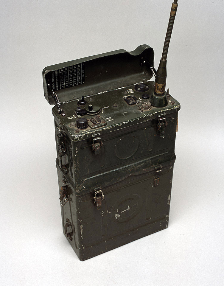
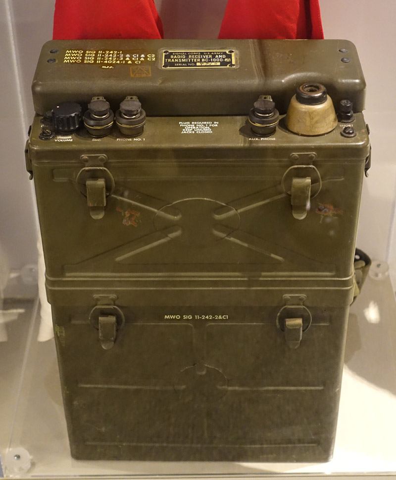
Wireless Set 31 is the British issued version of the Galvin (later Motorola) SCR-300. It is a man portable tactical low VHF FM voice set, its specifications here. It has only 0.3W RF output; this is because tactical radios need to work over just so much distance and no more, lest others overhear. The quoted range is 3 miles, dependent upon terrain and antenna.
This equipment was the first ever to be called a ‘walkie-talkie’, and featured in D-Day. There was also a vehicle mobile variant; this variant appears to have survived better than the infantry type and is more commonly found in collections.
Wikipedia says:
Colonel Ankenbrandt informed General Meade that “they are exactly what is needed for front line communications in this theater”. In his point of view, the main difficulty was keeping them supplied with fresh batteries.
Alas by this hangs, heavily, a tale. The set could be powered by either of the BA-70 or BA-80 battery packs. These were specially made by a subcontractor and were dry battery packs of different capacities configured to deliver the three voltages (4.5, 90, 150) required by the set and provided with the connector to match it. Either battery pack could be attached underneath the set to make a reasonably man portable if rather heavy small-rucksack sized item. The heavier BA-70 together with the set weighed nearly forty pounds (17.34kg).
Unfortunately as Colonel Ankenbrandt discovered these battery packs were difficult to obtain even during WWII as the subcontractor became progressively less able to supply them. Since WWII they have of course been completely unobtainable even by museums, who habitually exhibit empty battery casings.
Accordingly and with a sort of Royal Engineers attitude a technical fix was duly put in.
31 Set empty battery casings being available a sufficiency had been obtained to provide each set with two battery casings instead of one. If memory serves me right they were of slightly different heights so perhaps one was a BA-70 type and the other a BA-80. The combination of rig and two battery boxes stood the best part of three feet high.
This Magnum was permanently fastened to a ladder frame aluminium artefact called ‘Carrier Manpack Type 3’ (type 1 illustrated as no other photo found; type 3 I remember to be somewhat longer and narrower but stylistically very similar) and the two battery boxes were filled with dozens and dozens of tiny glass jar type 2V wet-cell accumulators, allegedly once intended to be used in threes to provide 6V for motor scooter electrics somewhere in Europe.
These accumulators were considerably smaller than the kind commonly used hitherto for domestic radio receivers, were rectangular rather than square in plan, lacked handles and had their two terminals and stopper in a straight line. There appears to be no photo of such things available. In theory there should have been 75 of these cells to each radio for 150V plate voltage but I never actually counted them. Nor did I ever weigh anything but making reasonable assumptions one might guess that the whole apparatus, radio, boxes, accumulators and carrier, could have weighed as much as thirty kilos, like a large and full bergen.
One was expected to carry this impressive item vertically and carefully so that none of the accumulators would spill (the stoppers were not perfectly reliable). This idea was of course somewhat incompatible with that of hurling oneself to the ground when fired upon.
There was a sort of yoga movement in which one would pick up the manpack from its position standing vertically on its bottom and carry it off, to deposit it later by a sort of reversal of this procedure, only I always found it much more difficult to put the thing down than to pick it up; perhaps that is why rather more than half a century later I have such a fine collection of hernias.
Having picked it up one was then expected to carry the thing to the exercise area, mostly woodland the property of a distant stately home and some two miles and three hundred or so feet of ascent away, to provide communications for some tactical purpose connected with an exercise. The Major made up all these exercises himself, demonstrating his imagination or possibly his taste in films, though many amounted to not much more than ‘Hunt the Slipper’. In the middle of the wood was a forester’s cottage occupied by an actual forester, also belonging to the stately home, who was remarkably tolerant of being woken up at absurd hours owing to his cottage being stormed by burnt cork adorned juvenile delinquents pointing firearms at him and demanding “Where’s the [richly decorated] Plutonium?”
In between such times the sets would be charged up, one at a time, by a contraption semi-concealed in the Major’s office as nobody else would give it house room. They were looked after technically, at least in theory, by the cosseted and pampered kulaks of the 19 Set Owners’ Club.
Alas by that hangs another tale. As the learned reader can no doubt imagine 75 (if it really was that number) little glass accumulators packed with waste paper and whatnot into their two metal boxes must be connected in series with a similar number of link wires in order to deliver their collective 150V and each and every terminal must be clean, tight and secure for this to happen.
Of course lugging the wretched thing a couple of miles in all weathers and generally handling it at all tended to ensure that things became filthy, loose and feral so having got it where it was wanted one would commonly find that it would not work. Quite often the set would wake up and pretend to be working, with the 4.5V heater voltage on, and might perhaps receive, with the 90V HT on, but would refuse to transmit owing to the 150V plate voltage being unavailable. We were not allowed to field strip and reassemble the sets and so if as usual one’s set did not work one simply had to carry it around, sometimes for a whole weekend, to no purpose, and then return it carefully as though it were still precious.
In the unlikely event of one’s set working the usual procedure was:
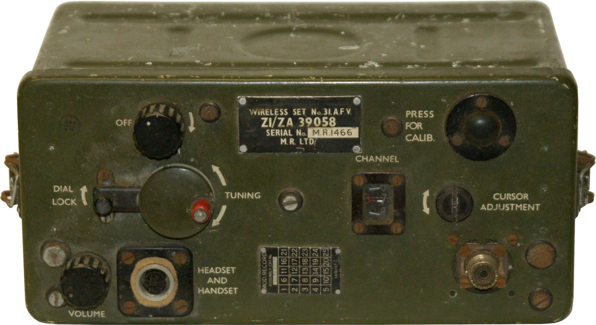
If it is not already fitted, attach antenna (about five feet long) to special connector (these unique items are nowadays often replaced by collectors with SO-239s as in the picture).
Connect handset or headset to special connector (there was just a tiny bit of standardisation in this as one of the headsets used with the 19 Set would also fit the 31).
Switch on rig with volume control and allow to warm up. Turn squelch off (if one does not do this one never hears anything).
Release the tuning dial lock and turn dial until the CAL indicator is visible in the tuning window (there are two possible calibration frequencies). Press the calibration button and adjust the tuning dial for minimum beat. Then, having released the button, with a coin or the rim of a round adjust the tuning scale cursor until it points exactly to the CAL indicator.
Tune rig to required frequency, lock dial and carry on.
Should this procedure be successful one would achieve FM voice comms with other sets a matter of hundreds of yards away; alas all the 19 Sets at HQ were on armoured rather than infantry frequencies and so net control always had to be another 31 Set, carefully selected and nurtured.
Having done all of this and against all odds found the thing working one would then find that its performance compared only modestly with anything else described as ‘communications equipment’.
One might compare the 31 Set with the modern Baofeng UV-5R which has two bands rather than one, sixteen times the power, at least twice the battery endurance, squelch that works and perhaps one seventy-fifth of the weight, all at an infinitesimal fraction of the cost.
Not long after this I moved to another school, which had no CCF but for no clear reason specialised in politics, to do ‘A’ Levels. Shortly before I left the 31 Sets started to be replaced with AN/PRC-10 portable VHF sets; I never saw one of these work at all.
]]>